Before you start
How to ideally use the PATCHBOX
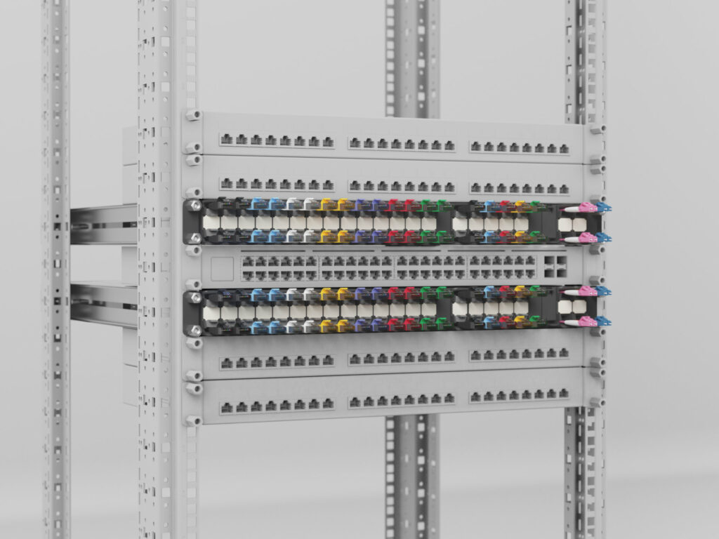
To get the most out of your network rack, we recommend sandwiching a 48-port switch between two PATCHBOX. When using a 24-port switch, place the PATCHBOX between the switch and patch panel. Try always to mount the PATCHBOX right next to your switch to get a 1:1 logic between cables and switch ports. Keep the distance to the network components short. As our Cassettes are available in three different cable lengths, use the correct position in the Frame to cover the required distances.
Our Cassettes can be used upside down in case the switch you are patching to is below your PATCHBOX, or flipping every second Cassette when patching a 24-port switch. Doing that ensures the straightening of the cables. Hence they don’t need to be turned or bent to be patched in the port.
Let’s start
Mounting the Mounting Rails
Mounting Rails only come with a PATCHBOX Plus+. If you want to install a PATCHBOX 365, please skip this step and continue at “Mounting the PATCHBOX/Frame with a /dev/mount”.
Step 1: You have two Mounting Rails – one for the left side, which should be marked with an “L” and one for the right side, which should have an “R” on it. The one end with one thread with a plastic tip on it is the back, which should go in first. The other end with two threads is the front, which should be facing you after you mounted the Mounting Rails.
Step 2: Take one Mounting Rail (don’t forget to use the correct one for whichever side you are starting with) and loosen the hex nut in the middle of the Mounting Rails to later extend it while mounting it.
Step 3: Now guide in the Mounting Rails with the black plastic tip first. This tip should be on the upper half of the rack unit. Note: Be careful that both Mounting Rails are on the same level on both ends. Otherwise, your hardware would be skewed.
Step 4: The other end of the Mounting Rail (with the two threads) should be on the same rack unit and placed in the 19” rail facing you.
Step 5: In case your Mounting Rails are too short, loosen the hex nut if you haven’t yet, and extend the Mounting Rail by pulling on one end.
Step 6: Now guide the other end into the threaded holes as described in step 4, fasten the hex nut of the Mounting Rail, and also fasten the Mounting Rail on the 19” rail with the hex nuts.
Step 7: Repeat the process on the other side of your 19” rail.
Mounting the PATCHBOX/Frame on the Mounting Rails
Step 1: Mount the Mounting Rails.
Step 2: There are hooks on both Mounting Rails, which should be facing inwards of the network rack. This hook will hold your PATCHBOX/Frame.
Step 3: To achieve that, carefully guide and slide in your PATCHBOX/Frame. The hook of the Mounting Rails needs to be hooked in the cutout provided for this purpose.
Step 4: The threads of the Mounting Rails should be put in the holes of the ears of the Frame. Now, add the Patchcatch on both sides between the rail and the Frame and take the hex nuts and fasten them.
Mounting the PATCHBOX/Frame with a /dev/mount
If you are installing a PATCHBOX 365, please read this instruction carefully. If you want to install a PATCHBOX Plus+ or a Frame with PATCHBOX Plus+ Cassettes, please use the Mounting Rails, not the /dev/mounts. You can find the installation instructions above.
Step 1: The /dev/mount fits in square punched hole racks with EIA-310 specifications. The maximum rating per RU is 15kg (33 lbs).
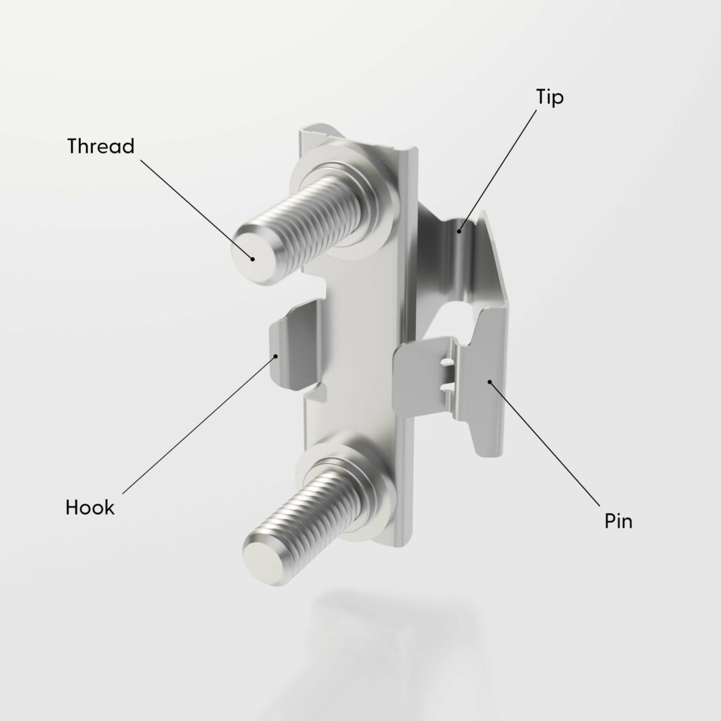
Step 2: How to hold the /dev/mount – place the middle finger on the very end of the /dev/mount, the tip, the index finger behind the top thread and the ring finger behind the bottom thread. The thumb should be placed on the clip.
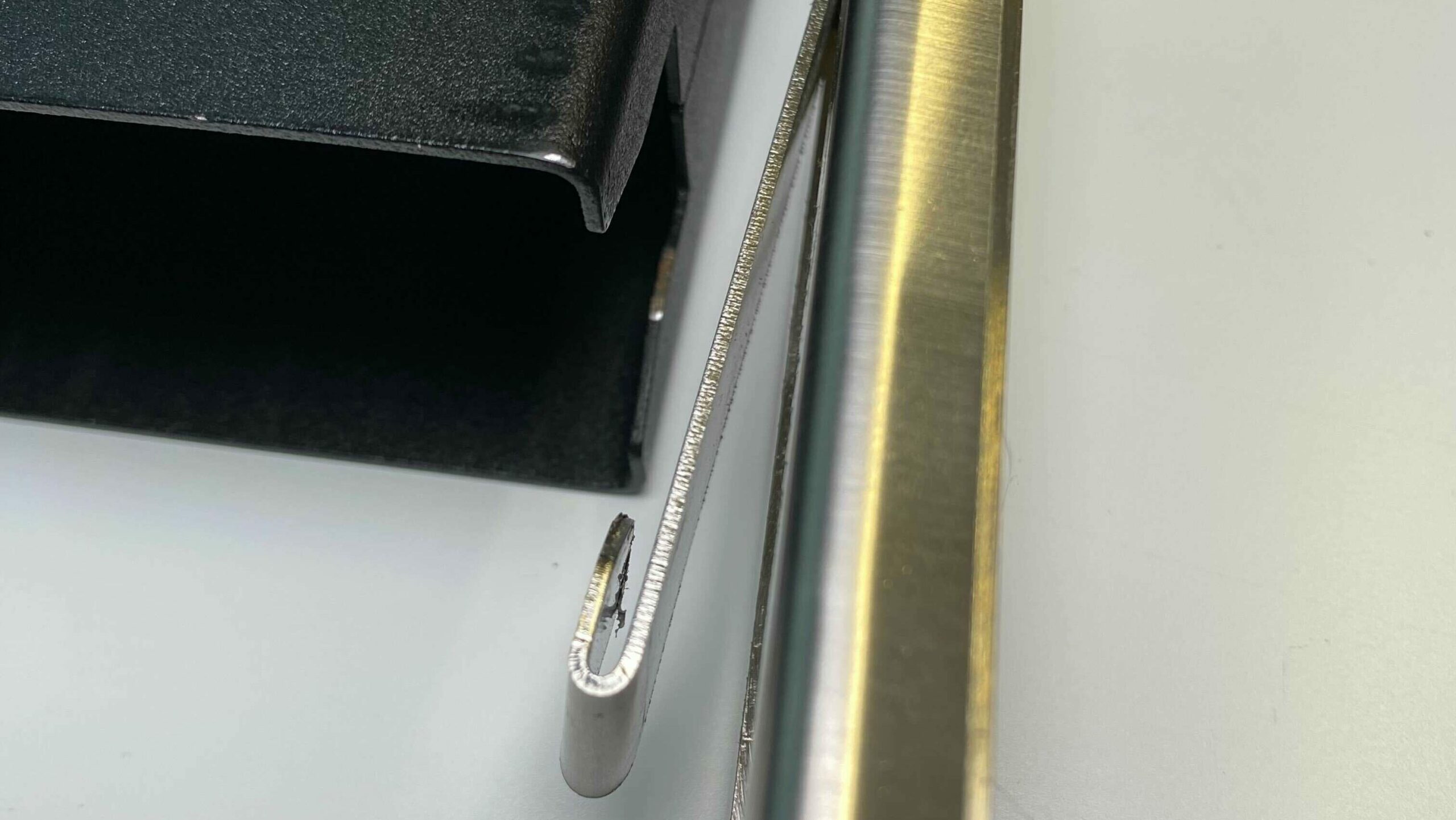
Step 3: Align the /dev/mount to the 19” rail with the threads facing you. Guide the /dev/mount in from behind the rail. The threads should align with the top and bottom hole of the rack unit, the hook going through the middle hole. The hook must lock with the rail.
Step 4: Make sure to hold the /dev/mount straight. Push the tip slightly towards you and while doing so use your thumb to push the front end of the clip from the side towards the 19” rail until it snaps in place.
Step 5: Now take the hardware (with 15kg or less) you want to install and place it on the threads of the /dev/mount.
Step 6: Take the hex nuts and fasten them by hand. Only by hand. Do not use tools to tighten the hex nuts! Maximum torque of 3Nm – more can deform your 19“ rail and/or your equipment.
Step 7: To dismount the /dev/mount push the tip from behind towards you and then slightly inwards the network rack. The snapped-in clip should let go. Remove the now lose /dev/mount from behind and take it out of the 19” rail.
Step 8: Take your Frame and slide it into the rack unit and onto the threads of the /dev/mount, with the rack ears facing towards you.
Step 9: Now, add the Patchcatch on both sides between the rail and the Frame and take the hex nuts of the /dev/mount and fasten them.
Mounting the Patchcatch
Step 1: Place the Patchcatch between the hardware/PATCHBOX and the 19” rail – or in case you have already installed it: Loosen the hex nut/screw used to fasten your hardware or your PATCHBOX. The hex nut/screw does not need to be removed! Loosening it a little is just fine.
Step 2: Slide the Patchcatch between the 19’’ rail and the hardware/PATCHBOX. The long clips of the Patchcatch should be facing away and to the sides of your network rack.
Step 3: Fasten the hex nuts/screws.
How to use the Frame
In case you own a complete system, the Frame will already be filled with Cassettes. If you ordered a Frame with individual Cassettes, your Frame will arrive empty. If your PATCHBOX is already assembled, you can skip the first 3 steps and continue at step 4.
Step 1: After successfully mounting the Frame, it is time to add your Cassettes. Take your Cassette upright with the cables facing you – with the tab of the RJ45 connector on top to patch to a switch above the PATCHBOX. Or with the RJ45 connector on the bottom if the switch you want to patch to is below your PATCHBOX. Doing this avoids bending the cable. When patching a 24-port switch, flip every second cassette upside down to avoid twisting the cable in the short run.
Step 2: Slide your Cassette into the Frame until you hear a click sound – this means your Cassette is locked into the Frame.
Step 3: Fill your Frame with your Cassettes.
Step 4: To remove a Cassette, squeeze its top and bottom lock to unlock it from the Frame. While squeezing both locks, simply pull the Cassette.
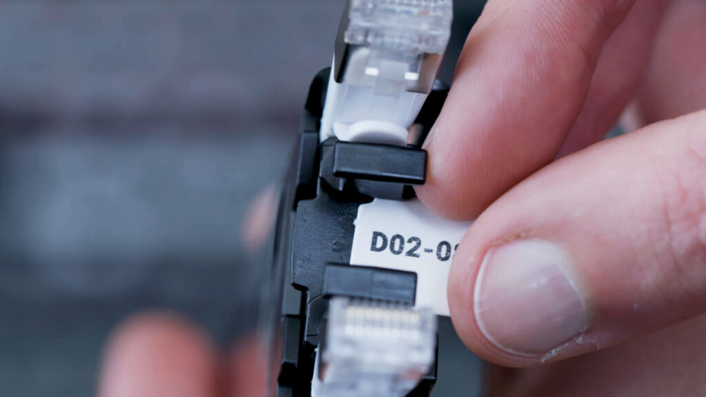
Changing a Cassette: How do I identify the patched cable?
Step 1: Check the ID Label and your documentation.
Step 2: If you are not using any documentation, hold the cable at the PATCHBOX Cassette you want to change and give it a careful wiggle. There should not be any tension on the cable, so it should wiggle a little. Follow the cable movement with your eye until you find the port it is patched to.
Locking & unlocking the cable stopper
Step 1: Have a close look at the front of your Cassettes. There are two bars and a rectangular area, or even an ID Label if you have already added one.
Step 2: Pull the bars to unlock the cable stopper. By doing this, the cables can be pulled out but also retracted.
Step 3: Push the rectangular area between the two bars (or if you have placed it there already, push the ID Label) to lock the cable stopper again.
Step 4: There should not be any tension on your cables. Patch your cable (within the specified range of rack units of your Cassette), then guide the cable to the Patchcatch in the same rack unit as the hardware you have patched to, then guide the cables to the Patchcatch in the same rack unit as your PATCHBOX – and don’t forget to lock the cable stopper at the end. If the switch is right above or below your PATCHBOX, you can skip the Patchcatch due to the short distance covered. And as you are using the Patchcatch you do not need any further cable managers. We highly recommend not using any cable management other than the Patchcatch – this likely will result in cable spaghetti and bad maintainability.
Step 5: To retract the cable, make sure you unlocked the cable stopper. If the cable stopper is still active, cables should not be pulled out, nor can they be retracted properly.
Step 6: The mechanism does not start automatically if you have unlocked the cable stopper. To activate it, pull the cable’s other (!) end until it reaches the same length (or as much cable length is left in the Cassette). When you release the cables, they will retract on their own. If there is still cable to be retracted, repeat step 6.
Editing the ID Label template
Step 1: Open the editable Template PDF with a PDF Reader (we recommend using Adobe Acrobat Reader, but it is also compatible with Google, Foxit Reader, and many more).
Step 2: Replace the text and write your documentation.
Printing the ID Labels
Step 1: Open your printer tray and remove all paper sheets. Place the ID Label A5 paper in your tray and close it.
Step 2: Modify your printer setting accordingly: “Portrait”, change the page size to A5, and “Scale: 100%”.
Step 3: Take the printed ID Label paper and push out the labels.
Inserting the ID Labels on a Cassette
Step 1: After you successfully edited and printed your ID Labels, it’s time to add them to your Cassette. Push the punched ID Label out of the sheet of paper.
Step 2: Look closely at the cable stopper on the front of your Cassettes. In between the two bars of the cable stopper is a rectangular area where the ID Label should be placed.
Step 3: Take your ID Label and slide it in from the side of the cable stopper until it is in place.
How do I patch and where should I patch to?
Step 1: To patch a cable, release the cable stopper. Do not pull a cable if the cable stopper is still locked.
Step 2: We recommend keeping the distance between the PATCHBOX and your switch short. Best case: The PATCHBOX is right above/below the switch.
Step 3: Patch your cable (within the specified range of rack units of your Cassette), then guide the cable to the Patchcatch in the same rack unit as the hardware you have patched to, then guide the cables to the Patchcatch in the same rack unit as your PATCHBOX – and don’t forget to lock the cable stopper at the end. If the switch is right above or below your PATCHBOX, you can skip the Patchcatch due to the short distance covered. And as you are using the Patchcatch you do not need any further cable managers. We highly recommend not using any cable management other than the Patchcatch – this likely will result in cable spaghetti and bad maintainability.
How to use the Blind Panels
Step 1: The Blind Panels do not have an up or downside, it can be used both ways. Hold it according to the image below.
Step 2: Apply a little bit of pressure and place the Blind Panel in an open space in your Frame – where you usually put a Cassette – to cover it.
Step 3: To remove the Blind Panel, simply repeat the process and pull it out.